Electrode diameter and amperage are linked decisions. A larger electrode can deposit more metal, but it needs more current, suitable access and tighter heat control. A smaller electrode is easier to control on thin material, root passes and difficult positions, but fills the joint more slowly. A sound choice considers thickness, joint design, electrode classification, welding position and WPS limits together.
What does electrode diameter change?
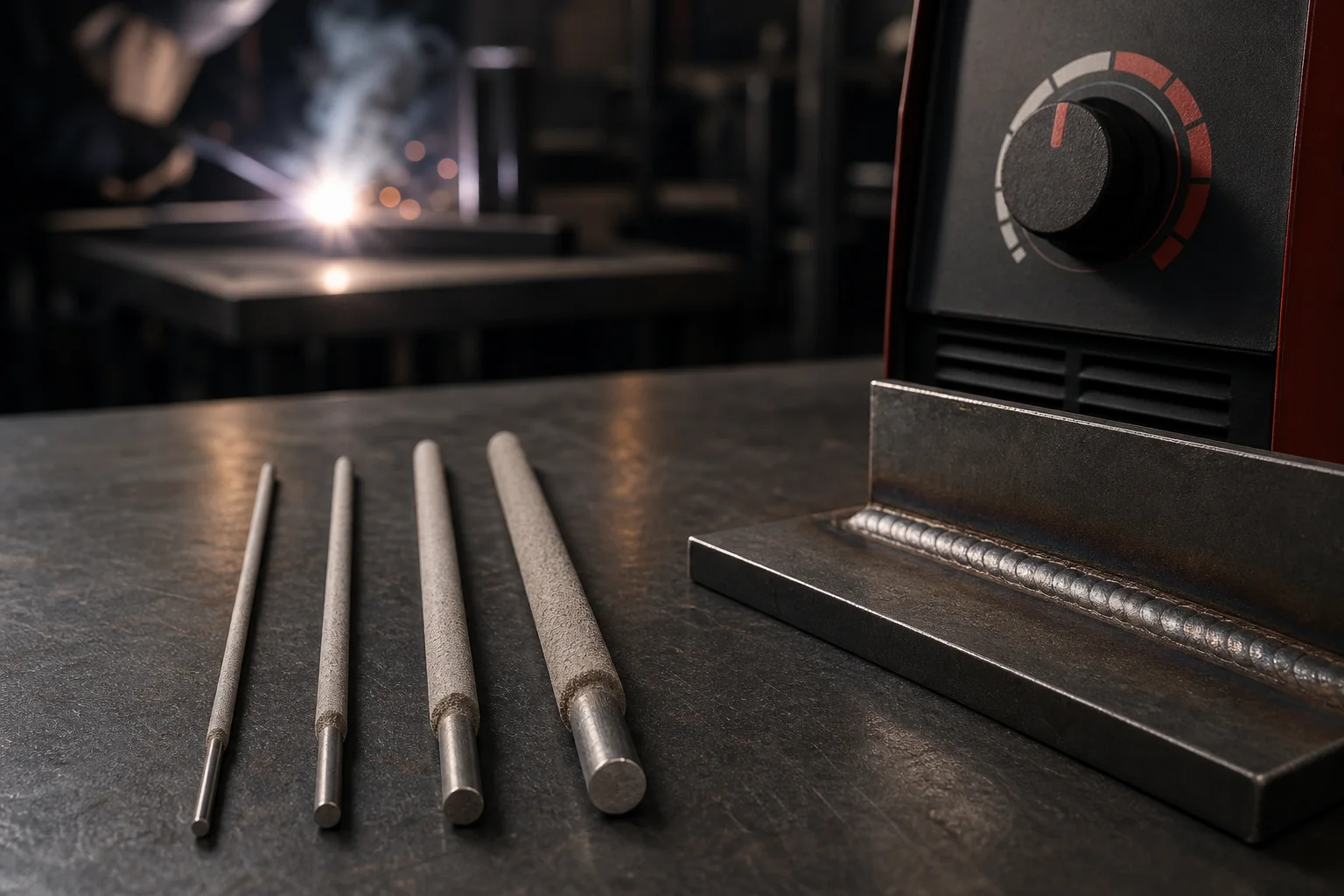
A larger core cross-section generally requires more current and can increase deposition rate and weld-pool size. The larger pool is harder to control vertically or overhead and raises burn-through and distortion risk on thin material.
- Smaller diameter: better pool control and root access, lower instantaneous heat and lower deposition.
- Larger diameter: faster deposition on heavy sections, with greater current and equipment demand.
- Electrode length: is separate from diameter, but resistance heating and handling can still affect arc behaviour.
Starting table for diameter and amperage
| Common diameter | Broad starting range | Typical use | Main consideration |
|---|---|---|---|
| 2.5 mm | About 55–95 A | Thinner material, repairs, small passes and difficult positions | Sticking risk at very low current |
| 3.2 mm | About 80–140 A | General fabrication, roots or fill depending on classification | Common workshop starting point |
| 4.0 mm | About 120–200 A | Heavier material and fill passes | Heat and position control become more important |
| 5.0 mm | About 180–280 A | High deposition, usually flat or horizontal on heavy joints | Requires suitable power source, leads and duty cycle |
The ranges are intentionally broad because coating type, arc length, polarity, position and manufacturer change the actual value. A stainless electrode may run lower than a carbon-steel electrode of the same diameter to control heat and coating temperature.
How does material thickness affect diameter?
Heavy material does not automatically require the largest electrode from the first pass. Groove design, root opening, edge preparation and pass sequence determine what fits. A thick joint may use a smaller root electrode followed by larger fill electrodes.
Thin material
A small diameter, short passes and controlled current reduce burn-through and distortion. Fit-up, gap and travel speed must remain consistent. Where the WPS permits, skip welding or a balanced sequence can control accumulated heat.
Medium thickness
A 3.2 mm electrode often offers useful flexibility for general fabrication. Classification still matters: E6010 and E7018 have different pool behaviour, so current cannot be selected from diameter alone.
Heavy sections
A 4 or 5 mm electrode may improve deposition provided position, preheat, maximum heat input, cables and power source allow it. Increasing diameter without adapting technique can cause incomplete sidewall fusion or slag entrapment.
Why vertical and overhead welding often use less current
In the flat position, gravity helps retain the pool and often permits a larger diameter or higher current. Vertical and overhead work benefits from a smaller, more controllable pool, so a smaller diameter and lower point within the approved current range are commonly selected.
Excessive reduction is not the answer. A weak arc can produce sticking and lack of fusion. The objective is a pool that provides both penetration and control.
How electrode type changes amperage
E6010: concentrated arc and root work
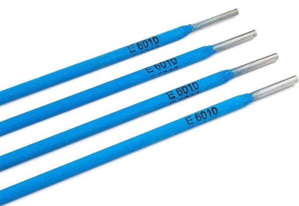
E6010 is a cellulosic electrode with a penetrating arc, commonly used on DCEP with a technique suited to pipe or root passes. Keyhole control, arc gap and travel speed matter as much as the displayed amperage. Applying a low-hydrogen baking practice to this electrode can damage its coating.
E7018: low-hydrogen pool and short arc
E7018 is normally used with a short arc within the manufacturer range. Low current promotes sticking and poor bead shape; excessive current can overheat the coating, increase spatter or undercut and complicate slag control. See the E7018 storage guide for handling requirements.
E316L-16: heat control in stainless steel
When welding with E316L-16, heat input and interpass temperature matter for distortion and heat-affected surface condition. Raising current simply to work faster can widen the pool and reduce control.
Polarity and current type
AC, DCEN and DCEP change heat distribution, arc stability and penetration. The classification and datasheet state which modes are permitted. If polarity is wrong, changing amperage may mask the symptom without correcting the process.
- Confirm electrode-lead and work-lead connections before welding.
- Long or undersized cables can create voltage drop and a difference between set current and arc behaviour.
- A machine display is not always equivalent to calibrated current at the arc; critical work needs verified measurement.
Selecting diameter for different pipe passes
A heavy pipe wall does not mean the largest electrode should be used from the first pass. Open roots and 5G or 6G work commonly need better access and a smaller, more controllable pool; fill passes may allow a larger diameter after the root is established and only within the qualified range. The table above is a starting point. See the root, fill and cap electrode guide for pipe for the complete decision sequence.
Signs of current that is too low
- Frequent sticking during starting or a short arc
- Unstable arc with repeated interruption
- Convex bead with poor sidewall wetting
- Insufficient penetration or fusion
- Poor slag movement and possible interpass entrapment
Signs of current that is too high
- Excessive spatter and harsh arc
- An overly fluid pool that is difficult to control
- Undercut, excessive bead width or edge burn-through
- Abnormal reddening of the remaining electrode or coating damage
- Greater distortion and heat input
These symptoms are not exclusive to current. Moisture, contamination, arc length, angle, travel speed and poor lead connections can produce similar behaviour.
A practical current-setting method
- Confirm classification, diameter, polarity and datasheet range.
- Review the WPS, thickness, position and heat-input limit.
- Start near the middle or lower part of the permitted range; vertical and overhead work generally start lower.
- Strike an arc on a coupon of matching material and thickness, not the production part.
- Observe stability, pool shape, penetration, bead edges and slag behaviour.
- Change current in small steps while keeping other variables stable.
- Record the effective setting and verify compliance with the WPS.
Do not overlook power-source duty cycle
Continuous use of larger electrodes can push a power source toward its duty-cycle limit. If the machine is not rated for the required percentage at that current, thermal protection may activate or components may be damaged. Leads, holder, work clamp and connectors must also be sound and rated for actual current.
Frequently asked questions
What diameter should be used on 3 mm plate?
It depends on joint design, gap, position and classification. A smaller diameter is generally easier to control, but the WPS or a representative coupon should confirm the decision.
Can amperage be calculated by multiplying diameter by one fixed number?
Rules of thumb are only starting points and ignore coating, classification, polarity and manufacturer differences. Datasheets and the WPS are more reliable.
Why does an electrode still stick inside the recommended range?
Check arc length, starting technique, lead connection, voltage drop, moisture and surface contamination. The display value is only one variable.
Conclusion
The right diameter creates a pool suited to thickness, position and joint design; the right current provides a stable arc, adequate fusion and acceptable control. Selection begins with the datasheet and WPS and is finalized through a controlled coupon test and observation of actual arc behaviour.
The ranges in this article are general educational values. Final parameters must follow the complete product classification, manufacturer instructions, approved WPS/PQR and project safety requirements.