ER70S-6 is one of the best-known solid carbon-steel wires for MIG/MAG welding and, in suitable product form, TIG welding. Ordering “70S-6 wire” alone is incomplete: process, diameter, shielding gas, package, surface condition and WPS all influence performance.
What does ER70S-6 mean?
- ER: electrode or filler rod, depending on process and product form.
- 70: the AWS tensile-strength class for deposited weld metal.
- S: solid wire.
- -6: a defined chemistry and classification group.
The code does not define diameter, spool weight, gas or machine parameters. Those details must be specified separately.
What base metals is it used for?
ER70S-6 is commonly used for many carbon and low-alloy steels in structural fabrication, general equipment, component production and repair, provided weld-metal strength and toughness meet the project specification. Unknown, galvanised, high-carbon or heat-treated steels require engineering review.
How does shielding gas affect performance?
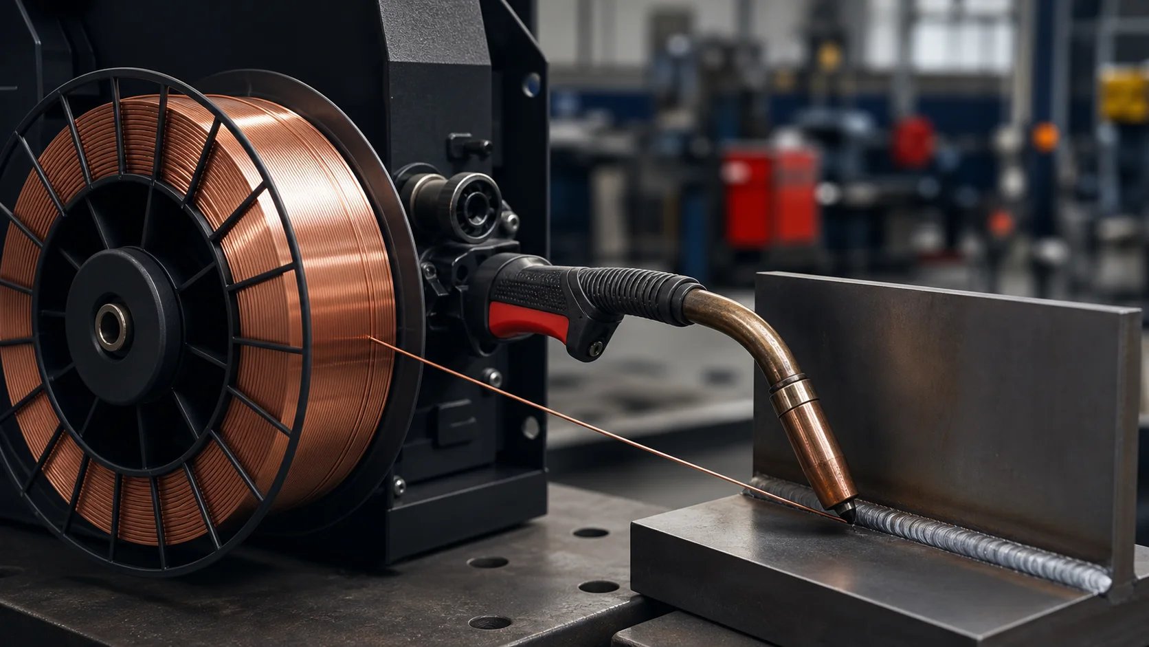
GMAW ER70S-6 may be used with carbon dioxide or argon/carbon-dioxide mixtures, but the arc does not behave identically. Gas selection affects penetration profile, spatter, arc stability, bead appearance and metal-transfer mode. The power source, diameter and WPS must support the selected gas.
| Topic | CO₂ | Argon/CO₂ mixture |
|---|---|---|
| General arc behaviour | Useful energy and penetration; spatter may be higher | Softer arc and improved spatter control, depending on mixture |
| Bead appearance | Strongly dependent on setting and technique | Often smoother within the correct parameter window |
| Final decision | Must follow WPS, transfer mode, cost and quality requirements | |
Choosing wire diameter
Smaller wire is generally suited to thinner material, lower current and tighter heat-input control. Larger wire can support higher deposition but needs a suitable power source, feeder and joint. One diameter is not optimal for every thickness or position.
The liner, drive roll and contact tip must match wire diameter. Incorrect rolls, excessive pressure or a dirty liner can cause slip, deformation and arc instability—problems sometimes blamed incorrectly on the wire itself.
Spool, drum or TIG rod?
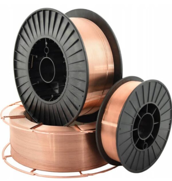
Standard spools offer flexibility for normal MIG/MAG use. High-consumption production lines may choose drums to reduce changeovers, but the feed path and payoff system must be designed for them. GTAW uses straight filler rods in specified diameter and length; the shared ER70S-6 classification does not mean identical packaging.
Surface and joint preparation
Better deoxidation is not permission to weld through contamination. Oil and paint generate gas, moisture increases porosity and hydrogen risk, while heavy mill scale and rust can destabilise the arc and contribute to fusion defects. Joint edges, root opening and tack welds must follow the procedure.
Common problems and troubleshooting
Porosity
Check gas leakage or flow, drafts, nozzle contamination, wet surfaces and excessive contact-tip-to-work distance.
Excessive spatter
Review voltage, wire-feed speed, polarity, work-return connection, gas and contact-tip condition.
Unstable feeding
Inspect drive rolls, roll pressure, liner, cable bends, spool brake and contact-tip size.
Lack of fusion or penetration
Review heat input, travel speed, torch angle, joint geometry and WPS limits.
Storage
Keep wire dry, clean and away from corrosive material. Damaged packaging, rust, oil contamination or surface discolouration should be assessed before use. Protect opened spools and drums from dust and humidity.
ER70S-6 enquiry checklist
- GMAW/MIG/MAG or GTAW/TIG process
- Exact wire or rod diameter
- Package type and weight
- Shielding gas
- Base-metal grade and thickness
- Position and joint type
- Project standard, WPS and impact requirements
- Quantity, delivery location and consumption plan
Voltage, amperage, feed speed and gas flow must match diameter, transfer mode, equipment and WPS. Do not apply one manufacturer’s parameter table to another product without verification.